A dedicated 4D phantom for MR-Linac time-resolved beam evaluation
PO-1739
Abstract
A dedicated 4D phantom for MR-Linac time-resolved beam evaluation
Authors: Lorenzo Placidi1, Cintia de Almeida Ribeiro2, Matteo Nardini3, Matteo Galetto2, Ivona Zlatkova2, Nicola Franza4, Luca Indovina3
1Fondazione Policlinico Universitario Agostino Gemelli IRCCS, Medical Physicist Department, Roma, Italy; 2Università Cattolica del Sacro Cuore, Facoltà di Medicina, Roma, Italy; 3Fondazione Policlinico Universitario Agostino Gemelli IRCCS, Medical Physics Department, Roma, Italy; 4Dosimetrica, Dosimetrica, Nocera Inferiore, Italy
Show Affiliations
Hide Affiliations
Purpose or Objective
MR-Linac allows tumor high accuracy online delivery tracking, with an IMRT step and shoot beam delivery technique solution. Beam symmetry and flatness are two beam parameters that should always been under control, especially when a tracking system is used for the delivery: therefore, the beam time-scale is relevant. Especially when different IMRT beams are employed, single beam MU’s value, can be very low and its optimization should be taken into account to avoid time related effect on the beam. The aim of this study is to firstly evaluate the time-resolved beam of a MR-Linac
Material and Methods
Square fields of 10x10 cm2 with a fixed gantry angle (350°) and fixed dose/rate (600MU/min) have been delivered with 6 MV FFF, 0.35 T MR-Linac system (MRidian, Viewray Inc). This field has been delivered with different MU (5, 10, 20, 40, 80, 100, 200, 300, 400, 500 and 600) on a dedicated and MR compatible device (Delta4 Phantom+ MR), for patient specific pre-treatment and machine QA. MU linearity has been firstly evaluated in terms of dose linearity error defined as ED=((L-LAve)/LAve) x100)%, where L is the dose per MU and LAve the mean dose per MU of the entire MU range (2-600 MU)). Linearity has been evaluated at three different depths: on the detector surface, at isocenter and at 10 cm depth from the isocenter, . Time/MU dependency of symmetry and flatness, both in-line and cross-line, have been computed and analyzed. Flatness and symmetry constancy refers to a reference 10x10 cm2 square field with 100 MU delivered at 350° gantry angle. Flatness and symmetry stability has been defined as the time/MU required to achieve four different levels: <0,1%, <0,2%, <0,5% and <0,8%.
Results
Maximum dose linear error setup was found for superficial and deepest depth for lower MU (<5). Isocenter dose linear error setup has been found to be always less than 1% for all MU. Table 1 reports, for the mentioned four stability levels and for a MU range of 10-600, the minimum value of time (s) needed to achieve such flatness or symmetry stability (both cross-line and inline). Also mean, maximum, minimum and standard deviation (SD) are reported respectively. Similar results can be also reported in terms of MU.
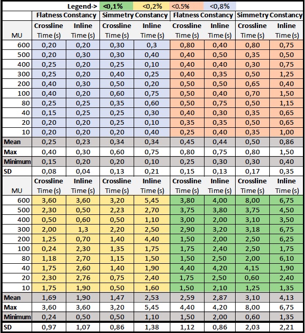
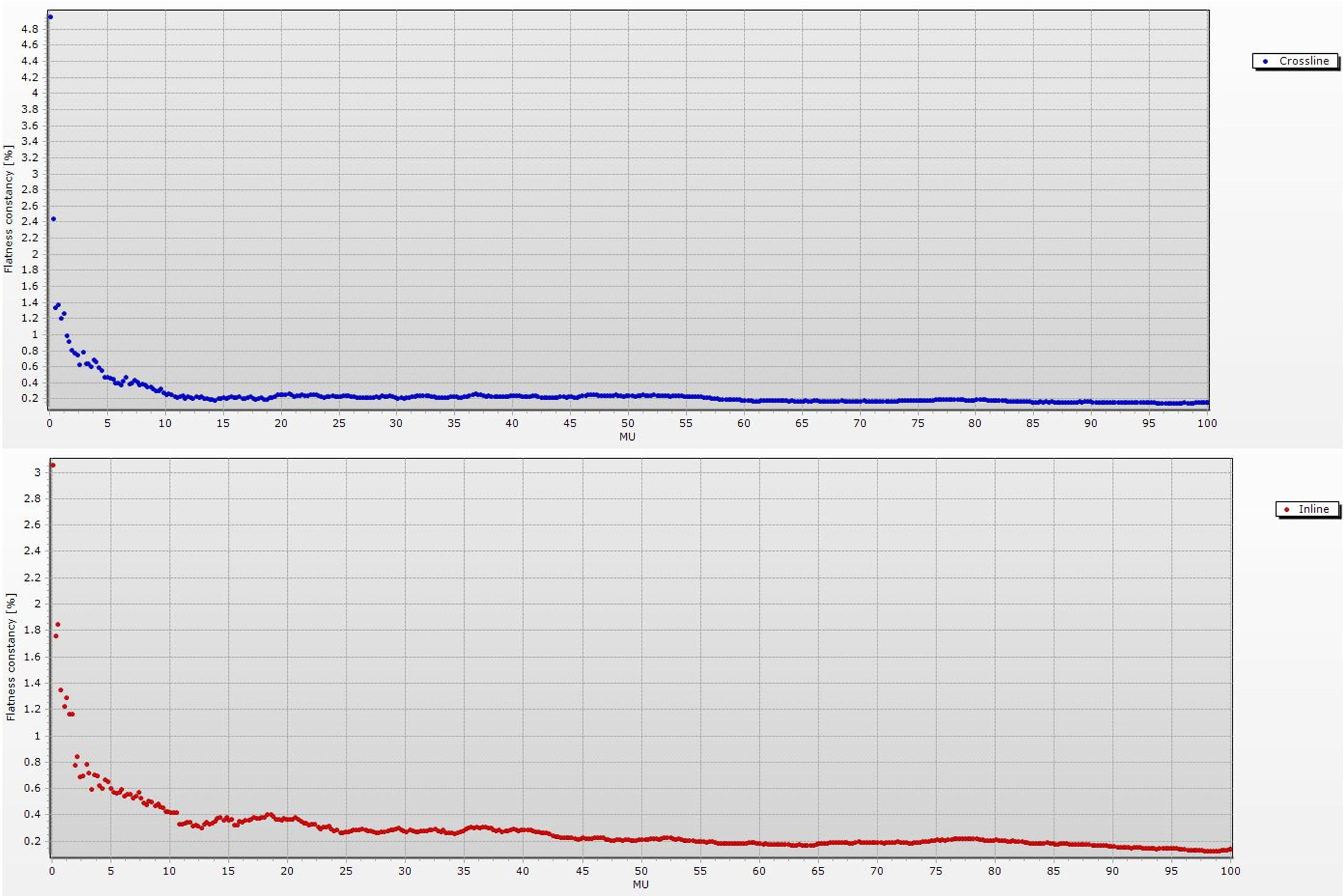
Concerning the straightest stability level (<0,1%), it reports a flatness constancy mean value of 8,4 MU and 7,7 MU; similarly, a symmetry constancy mean value of 8,1 MU and 8,15 MU (respectively crossline and inline). Delta4 software interface already provides a visualization of such parameters, as shown in figure 2, this time with respect to the needed MU to achieve the flatness and symmetry stability, for the cross-plane and in-plane 10x10 cm2 with 100 MU.
Conclusion
the obtained time-resolved beam evaluation highlights the minimum time/MU required to achieve flatness and symmetry constancy. Such values should be employed during the planning and optimization processes, also considering online plan adaptation and the need for such information in the system TPS.