Dosimetric characterization of a 12 cm IORT applicator of a Liac 12MeV linac
PO-1637
Abstract
Dosimetric characterization of a 12 cm IORT applicator of a Liac 12MeV linac
Authors: Rafael Ayala1, Gema Ruíz1, María Jesús García1, M. Susana Gómez1, Rocío Jiménez1, Teresa Valdivielso2, José Luis Navío1, Esmeralda Martínez1
1H.G.U. Gregorio Marañón, Servicio de Dosimetría y Radioprotección, Madrid, Spain; 2Hospital de Terrassa, Servicio de Radioterapia, Terrassa, Spain
Show Affiliations
Hide Affiliations
Purpose or Objective
The Liac 12
MeV accelerator (SIT) is supplied with cylindrical applicators with diameters
ranging from 3 to 10 cm. It is however possible to purchase a 12 cm diameter
applicator which is indicated for intraoperative radiotherapy (IORT) of large
lesions, such as sarcomas of the extremities.
The objective of this work is to provide a full dosimetric characterization of the 12 cm applicator with its four possible bevel endings and compare it with the regular applicators.
Material and Methods
This study was carried out on a SIT accelerator model Liac 12 MeV with nominal energies of 6, 8, 10 and 12 MeV. The distal part of all applicators ends in 4 possible bevel angles: 0, 15, 30 and 45º.
All measurements were performed in water with an IBA Blue Phantom 2 beam analyzer and the IBA PPC05 and PTW 60019 microDiamond detectors.
The measurements performed comprise PDDs, OARs at maximum dose and R90 depths and field factors (FF) at maximum dose depth for the four accelerator energies.
In addition to that, a Monte Carlo modeling of the accelerator/applicator assembly has been carried out with the code PENELOPE 2018 (Nuclear Energy Agency) that completes the previous modeling of the other applicators.
Results
The combination
of the 12 MeV energy together with the 12 cm applicator shows an irregular 90%
isodose volume in water, moving away from the surface outside the central axis
(fig 1). As the bevel angle is increased, the 90% isodose is reduced. When the
45º bevel is applied, the latter isodose is very small compared to the size of
the applicator (9cm in one of the directions at zmax depth). This
effect is less dramatic when decreasing the energy of the beam.
The field
factors show a downtrend similar to the other applicators as can be seen in
figure 2. When selecting the 12 MeV energy, the FF of the 12 cm applicator is
12% and 42% lower than those of the 10 cm and 5 cm applicators respectively.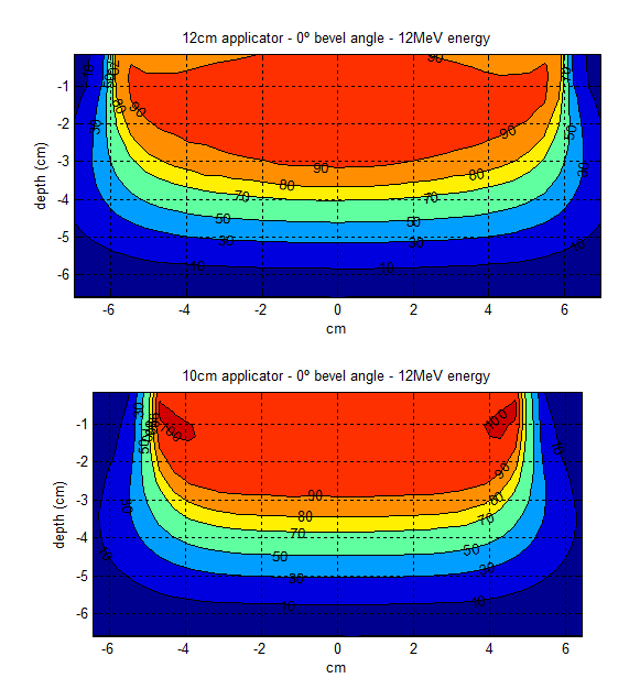
Fig 1: Transversal
plane isodoses in water calculated with PENELOPE 2018 MC code. 12 cm applicator
– 0º bevel vs. 10 cm applicator – 0º bevel, 12 MeV nominal energy.
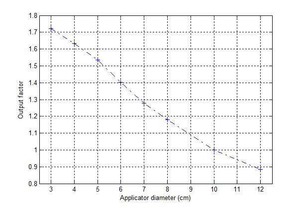
Fig 2: 12 MeV output factors in water measured
at the depth of maximum dose.
Conclusion
The 12 cm
applicator on some energy/bevel combinations does not meet what it is expected
from an IORT accelerator. When the energy is high and the bevel angle is increased,
the 90% isodose does no longer cover the surface of the tissue. If the
prescription dose is adjusted to mitigate this effect, then hot spots would be
added to the dose distribution.
Regarding field
factors, it is important to bear in mind that a treatment with the 12 cm
applicator involves longer irradiation times compared to the other applicators.